
Manipulator
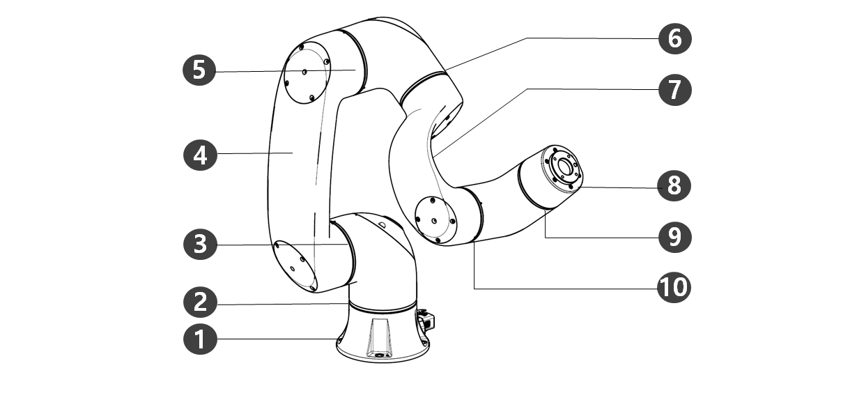
Names of Parts
|
No. |
Name |
No. |
Name |
|---|---|---|---|
|
1 |
Base |
6 |
J4 |
|
2 |
J1 |
7 |
Link2 |
|
3 |
J2 |
8 |
Tool Flange |
|
4 |
Link1 |
9 |
J5 |
|
5 |
J3 |
10 |
J6 |
Key Features
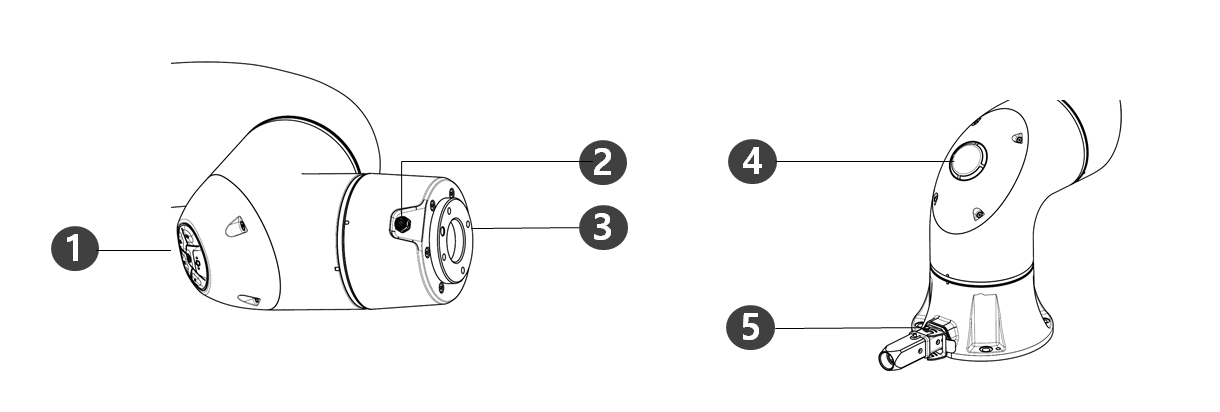
|
No. |
Item |
Description |
|---|---|---|
|
1 |
Cockpit |
Controller used for direct teaching. |
|
2 |
Flange I/O |
I/O port for tool control.
|
|
3 |
Tool flange |
Area to install tools. |
|
4 |
LED (1-axis) |
Displays the robot state with different colors. For more information about robot state, refer to the “ Status and Flange LED Color for Each Mode ” |
|
5 |
Connector |
Used for supplying power to and communication of the robot. |
Controller
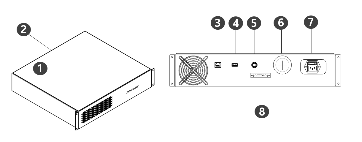
|
No. |
Item |
Description |
|---|---|---|
|
1 |
I/O connection terminal (internal) |
Used to connect the controller or peripherals. |
|
2 |
Emergency stop button and Smart Pendant connection terminal |
This connects the emergency stop button or Smart Pendant cable to the controller. |
|
3 |
Network connection terminal |
External Internet, TCP/IP equipment and Modbus equipment can be connected to the network router inside the controller. |
|
4 |
USB connection terminal |
Logs generated during robot operation can be saved to a USB storage device, or tasks can be exported or imported. |
|
5 |
Emergency stop button and Smart Pendant connection terminal |
This connects the emergency stop button or Smart Pendant cable to the controller. |
|
6 |
External cable terminal |
Terminal that can connect external devices. |
|
7 |
Power connection terminal |
This connects power to the controller. |
|
8 |
Manipulator cable connection terminal |
This connects the cable of the manipulator to the controller. |
Emergency Stop Button
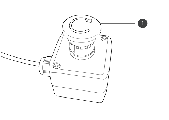
|
No. |
Item |
Description |
|---|---|---|
|
1 |
Emergency stop button |
In case of an emergency, press the button to stop robot operation.
|
Smart Pendant
The smart pendant is not a standard item but an optional item, so it must be purchased separately
For detailed product features, please refer Appendix. Smart Pendant (A Series).
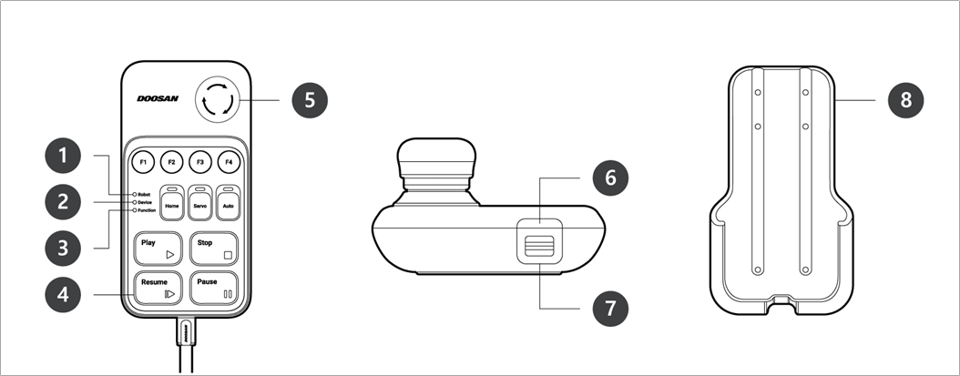
|
No. |
Item |
Description |
|---|---|---|
|
1 |
Robot LED |
Used to indicate the robot’s state by displaying the same color as the robot status LED to the user. |
|
2 |
Device LED |
Used to indicate whether the system entered smart pendant mode. |
|
3 |
Function LED |
Pressing four input signal buttons (F1-F4) lights the LED, indicating the press status. |
|
4 |
Buttons |
There are a total of 11 buttons including four input signal buttons (F1-F4) for each function, home, servo, auto, play, stop, resume and pause. |
|
5 |
Emergency Stop Button |
In case of an emergency, press the button to stop robot operation. |
|
6 |
Power Button |
Used to turn ON/OFF the main power of the smart pendant. |
|
7 |
Strap Anchor |
Used to add a strap to the device. |
|
8 |
Holder bracket |
Install the holder bracket on a wall to store the smart pendant. |
-
For using SW V2.8 or higher, please attach the Reset label to the Resume button on the smart pendant.
-
If a version lower than SW V2.8 is used, the reset label does not need to be attached. In that version, The resume button in Smart Pendant works as a resume function, not a reset function.
-
The label may come off during use, so please be careful.