
Manipulator
Names of Parts
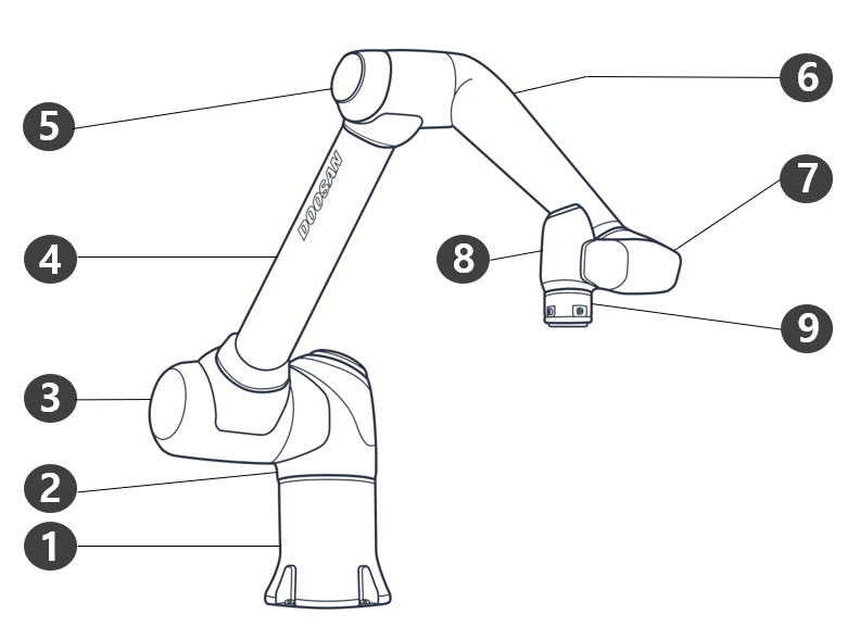
|
No. |
Name |
No. |
Name |
|---|---|---|---|
|
1 |
Base |
6 |
Link2 |
|
2 |
J1 |
7 |
J5 |
|
3 |
J2 |
8 |
J6 |
|
4 |
Link1 |
9 |
Tool Flange |
|
5 |
J3 |
10 |
|
Key Features
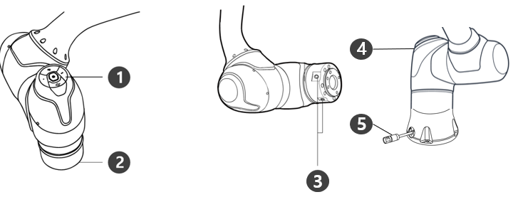
|
No. |
Item |
Description |
|---|---|---|
|
1 |
Cockpit |
[Option] Controller used for direct teaching and operation. |
|
2 |
Tool Flange |
Area to install tools. |
|
3 |
Flange I/O |
I/O port for tool control. (Digital input 3ch, output 3ch) |
|
4 |
LED |
Displays the robot state with different colors. For more information about robot state, refer to the Status and Flange LED Color for Each Mode |
|
5 |
Connector |
Used for supplying power to and communication of the robot. |
Controller
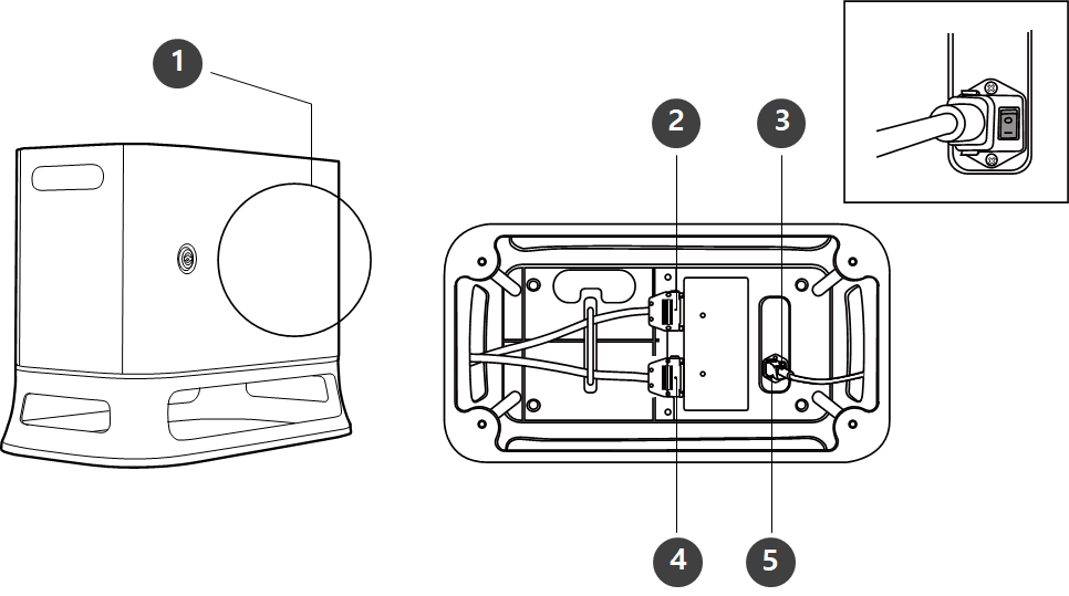
|
No. |
Item |
Description |
|---|---|---|
|
1 |
I/O connection terminal (internal) |
Used to connect the controller or peripherals. |
|
2 |
Teach pendant cable connection terminal |
Used to connect the teach pendant cable with the controller. |
|
3 |
Power switch |
Used to turn ON/OFF the main power of the controller. |
|
4 |
Manipulator cable connection terminal |
Used to connect the manipulator cable to the controller. |
|
5 |
Power connection terminal |
Used to connect the controller power supply. |
-
If you selected an optional controller, check the instructions in the appendix to connect cables.