
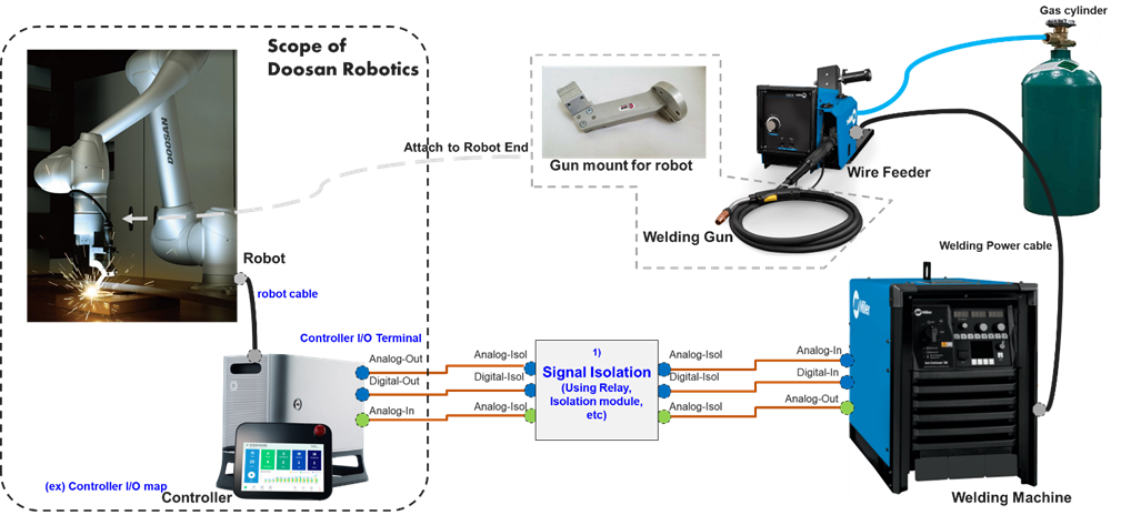
When connecting the welder's analog and digital in/out sockets with the controller, signal isolation is required to protect the circuits of the controller. Circuit separation is usually achieved by using a relay or isolation module. A direct connection may damage the circuits of the controller.
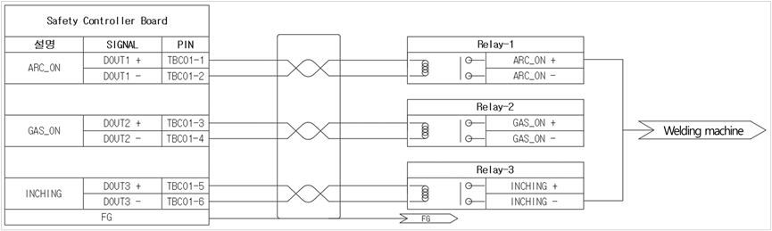
Example of a digital out connection using a relay
-
Digital output channel numbers are temporary numbers used for explanatory purposes.
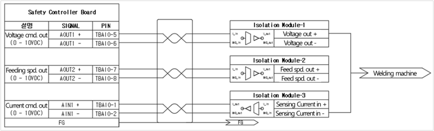
Example of an analog input/output connection using a commercial isolation module
-
Channel numbers of analog input/output are temporary numbers used for explanatory purposes.
-
Identical isolation is required for connections with additional welding machines.
-
If a separate external sensor for welding current measurement, such as a hall sensor, is used, there is no need for an isolation module.
-
In the case of an analog output, check the analog input signal specification (voltage) of the welding machine to determine which isolation module to use.
-
Refer to the table below for an example of a commercial isolation module. A module with identical specifications from a different manufacturer can also be used.
Manufacturer
Weidmuller
Type
WAS4 VVC DC 0-10V/0-10V
Description
0-10 V input, 0-10 V output
Refer to the for the electrical specifications of the control box.